A Guide to Select the Right Industrial X-ray / CT Inspection System for Effective Non-Destructive Testing (NDT)

Industrial X-ray and Computed Tomography (CT) systems are indispensable tools for non-destructive testing (NDT) and ensuring quality assurance across various industries. These inspection systems provide detailed insights into the internal structures of materials and components, helping to identify defects and verify integrity without causing damage. Selecting the most suitable industrial X-ray or CT system which meets the inspection requirements is critical for achieving accurate, efficient, and cost-effective inspections. This post will guide you through about the different types of components in the system, their main features, and how they affect the results.
X-ray Sources
The X-ray source is the heart of the industrial X-ray and CT system. Different inspection requirements demand different characteristics from the X-ray source.
1. X-ray tubes and their capabilities
1-1. Microfocus X-ray Tube
A microfocus X-ray tube has a focal spot size of 1–50µm(micrometers), enabling high-resolution imaging for detecting small defects. These tubes are engineered to produce a very small focal spot, which translates to high detail resolution in the resulting X-ray images and CT scans. They are often used to inspect intricate small electronic components, advanced semiconductors, and various materials in research and development environments. Certain microfocus tubes can achieve detail detectability down to the submicron level (less than 0.3 µm) Some models equip water-cooling to enhance the stability of the focal spot, leading to improved CT results and greater repeatability.
✔ Pros:
✅ High-resolution images – Ideal for fine defect detection
✅ Small focal spot – Reduces image blur and enhances sharpness
✅ Best for detailed inspections – Used in connectors or the other electronics components, PCB includes as BGA balls and blind via as well as small resin or aluminum casting parts
❌ Cons:
🚫 Lower X-ray intensity – Less effective for thick materials
1-2. Nanofocus X-ray Tube
A nanofocus X-ray tube takes microfocus technology further, with a focal spot size below 1µm, achieving ultra-high-resolution imaging. These advanced X-ray sources can achieve detail visibility down to the nanometer range (e.g., ≥ 150 nm), allowing for the detection of incredibly small defects.
✔ Pros:
✅ Extremely high resolution – Detects the smallest defects
✅ Perfect for advanced micro-inspections – Used in semiconductor analysis, high-precision CT scanning, and microelectronics
❌ Cons:
🚫 Very low penetration power – Not suitable for thick or dense materials
🚫 More sensitive to operational conditions
1-3. Minifocus X-ray Tube
A minifocus X-ray tube has a focal spot size of 50–500µm, offering a balance between image resolution and penetration power. In contrast to microfocus options, minifocus X-ray tubes typically offer higher power output, making them better suited for penetrating denser and larger samples. While they may have larger focal spots compared to microfocus tubes, potentially involving a slight trade-off in ultimate resolution, their increased penetration power is crucial for certain applications.
✔ Pros:
✅ Higher X-ray intensity – Suitable for thicker materials
✅ Ideal for industrial applications – Used in weld inspection, castings, and large structural components
❌ Cons:
🚫 Lower resolution compared to microfocus and nanofocus tubes
🚫 Not suitable for detecting extremely fine defects
1-4. Mesofocus X-ray Tube
A mesofocus X-ray tube has a focal spot size between 50–300µm, MesoFocus X-ray tubes are designed to bridge the gap between microfocus and minifocus technologies, Balancing Power and Resolution. They offer a beneficial combination of robustness, high energy levels, and relatively good spatial resolution through the availability of multiple selectable focal spots. This balance makes them particularly advantageous for challenging industrial environments and can simplify operation for less experienced users.
✔ Pros:
✅ Stronger X-ray intensity than microfocus – Suitable for mid-thickness materials
✅ Better resolution than minifocus – Provides a balance between detail and penetration
✅ Ideal for castings, composites, and mid-size industrial components
❌ Cons:
🚫 Lower resolution than microfocus and nanofocus tubes
🚫 Not as powerful as minifocus for very thick materials
1-5. Multifocus X-ray Tube
Adaptability for Diverse Inspections. Some sophisticated industrial X-ray/CT systems can be equipped with multifocus X-ray tubes, providing users with the flexibility to switch between different focal spot sizes. This adaptability allows for optimization based on the specific inspection task, choosing a smaller spot for high resolution or a larger spot for increased power.
 X-ray Tube Configuration
Single vs. Dual X-ray Tube Systems for Enhanced Versatility
Advanced industrial CT systems can feature dual X-ray tube configurations for maximum versatility. These systems can combine different X-ray tube types (for instance, a high-resolution nanofocus tube alongside a high-power microfocus tube) within a single machine. This design allows users to precisely tailor the X-ray source characteristics to the specific requirements of each unique inspection task without the need for multiple systems.
Which X-ray Tube To Choose?
- For ultra-high precision and micro-defect detection → Nanofocus
- For high-resolution industrial inspections → Microfocus
- For mid-thickness materials requiring both resolution and penetration → Mesofocus
- For general industrial use with thick and dense materials → Minifocus
Selecting the right X-ray tube ensures optimal image quality, defect detection accuracy, and efficiency in non-destructive testing (NDT) applications.
2. How X-ray Tube Voltage (kV), Tube Current (A), and Power (W) Affect X-ray Results
2-1. X-ray Tube Voltage (kV) – Controls Penetration Power
Kilovoltage (kV) refers to the energy level of the X-ray beam. A higher kV means higher energy X-rays, which penetrate thicker and denser materials.
✔ Effects of Increasing kV:
✅ Greater penetration – Ideal for thick or dense materials like metals
✅ Lower contrast – High-energy X-rays reduce material differentiation
✅ Shorter exposure time – Increases efficiency for high-throughput inspections
✔ Effects of Decreasing kV:
✅ Higher contrast – Better for detecting fine defects in thin materials
✅ Reduced penetration – Suitable for low-density materials like plastics or composites
2-2. X-ray Tube Current (A) – Controls Image Brightness & Exposure
Tube current (measured in milliamperes, mA, or amperes, A) determines the amount of X-ray photons produced. A higher current generates a brighter image but does not increase penetration.
✔ Effects of Increasing mA:
✅ Brighter images with more intensity
✅ Improves signal-to-noise ratio (SNR), reducing grainy images
✅ Better for thick materials where more photons are needed
✔ Effects of Decreasing mA:
✅ Reduces exposure dose and heat generation
✅ Lower cost and longer X-ray tube life
✅ Better for materials where excessive exposure can cause damage
2-3. X-ray Tube Power (W) – Controls Exposure Time & Imaging Speed
Power (W) is calculated as:
Power (W) = Voltage (kV) × Current (mA)
Higher power allows faster exposure times, improving inspection speed and efficiency. However, excessive power may overheat the tube, requiring cooling systems.
✔ Effects of Increasing Power:
✅ Faster imaging and reduced scan time
✅ Better for high-throughput inspections
✅ Needed for large parts requiring deep penetration
✔ Effects of Decreasing Power:
✅ Extends X-ray tube lifespan
✅ Better for detailed, long-exposure inspections
✅ Reduces thermal stress on the X-ray system
3. Transmission Tube vs. Reflection Tube
3-1. Transmission-Type X-ray Tube
A transmission-type X-ray tube generates X-rays by passing them through a thin target, producing a small focal spot size for high-resolution imaging.
✔ Pros:
✅ High resolution – Ideal for detecting fine defects
✅ Small focal spot size – Improves image sharpness
✅ Best for micro and precision inspections
❌ Cons:
🚫 Lower penetration power – Less effective for thick materials
🚫 Typically has a shorter lifespan compared to reflection-type tubes
3-2. Reflection-Type X-ray Tube
A reflection-type X-ray tube produces X-rays by reflecting them off a thick target, allowing for higher energy and greater penetration.
✔ Pros:
✅ High penetration power – Ideal for thick or dense materials
✅ Longer lifespan – More durable for continuous industrial use
✅ Best for heavy-duty inspections
❌ Cons:
🚫 Larger focal spot – May reduce image sharpness
🚫 Less suitable for high-precision, small-scale inspections
Which X-ray Tube to Choose?
- For high-resolution, fine-detail inspections → Transmission-type X-ray tube
- For deep penetration and large industrial parts → Reflection-type X-ray tube
Choosing the right X-ray source ensures better image clarity, defect detection accuracy, and optimal performance in non-destructive testing (NDT) applications.
X-ray/CT Detectors
The detector in an industrial X-ray system or CT system plays a critical role by capturing the X-rays that have passed through the sample and converting them into a signal that can be processed to generate an image. The choice of detector has a significant impact on the resulting image quality, inspection speed, and overall suitability of the system for different non-destructive testing applications.
4. Understanding the X-ray Detector Types
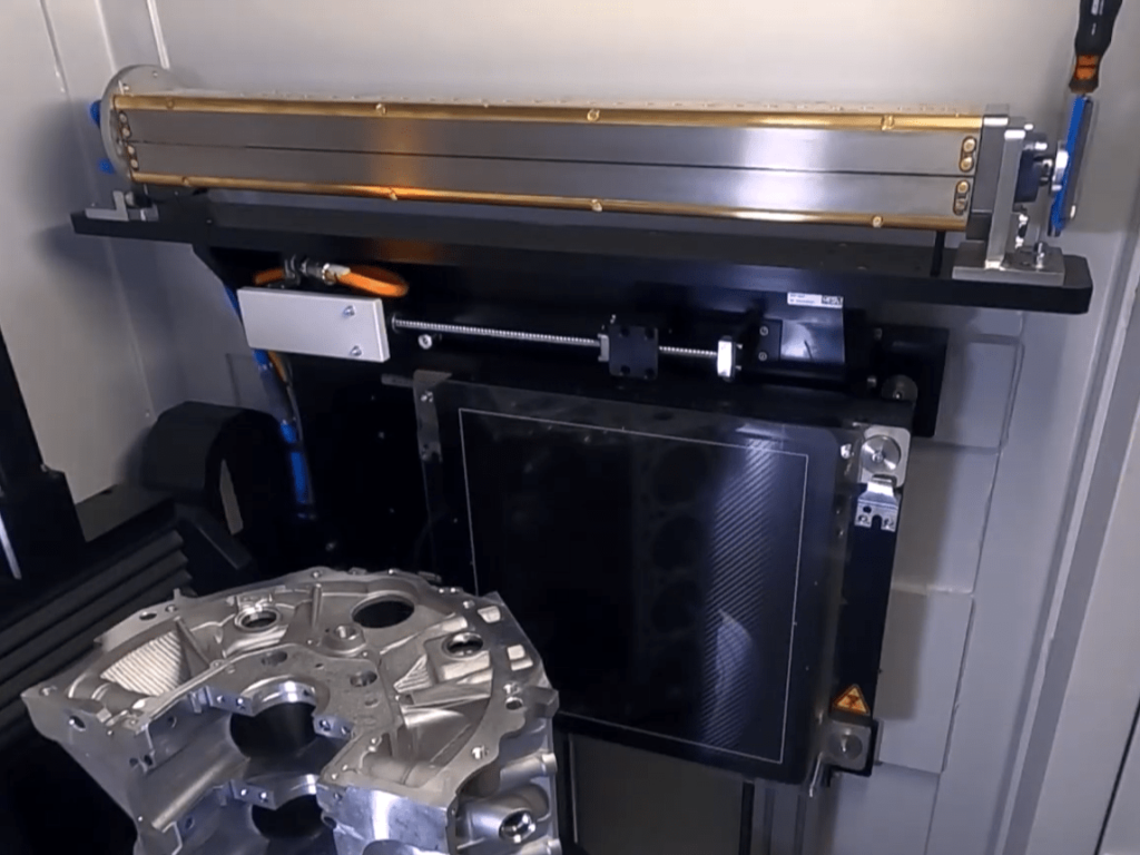
 4-1. Flat Panel Detector (FPD)
A Flat Panel Detector (FPD) is the most advanced digital X-ray detector, offering high-resolution images with a wide dynamic range.
Pixel Pitch and Matrix Size: Defining Image Detail. A smaller pixel pitch (the size of each individual sensor element) and a larger pixel matrix (the total number of pixels) directly contribute to higher spatial resolution and the ability to capture finer details in the images. For example, some advanced FPDs offer pixel pitches down to 139 µm or even smaller.
Active Area / Field of View: Imaging Larger Samples. The active area of the detector defines the field of view (FOV), which is the size of the sample that can be imaged in a single scan. Detectors with larger active areas enable the inspection of larger parts or the acquisition of more comprehensive data in a single pass, potentially reducing the need for multiple scans or part repositioning. Some flat-panel detectors can have an active area of 430 x 430 mm or more.
✔ Pros:
✅ High image quality and detail
✅ Fast digital output, reducing inspection time
✅ Suitable for both 2D X-ray and 3D CT scanning
❌ Cons:
🚫 Higher cost compared to other detectors
🚫 Larger file sizes require more storage and processing power
4-2. Image Intensifier (II)
An Image Intensifier (II) uses a vacuum tube system to amplify X-rays into visible light, which is then captured by a camera. While this technology has been widely used, it is gradually being replaced by FPDs due to its limitations in image quality.
✔ Pros:
✅ Lower cost compared to FPDs
✅ Faster image processing than CR systems
❌ Cons:
🚫 Lower image resolution, with distortion at the edges
🚫 Bulky and requires regular maintenance
4-3. Computed Radiography (CR) System
A Computed Radiography (CR) System uses phosphor imaging plates instead of traditional film. The plate captures the X-ray image and then must be scanned for digital conversion. CR is more cost-effective than FPDs but slower and lower in resolution.
✔ Pros:
✅ More affordable than FPDs
✅ Plates are reusable and portable
❌ Cons:
🚫 Longer processing time compared to digital detectors
🚫 Lower resolution and dynamic range compared to FPDs
 4-4. Line Detector Arrays (LDA)
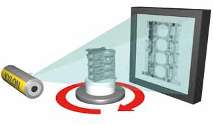
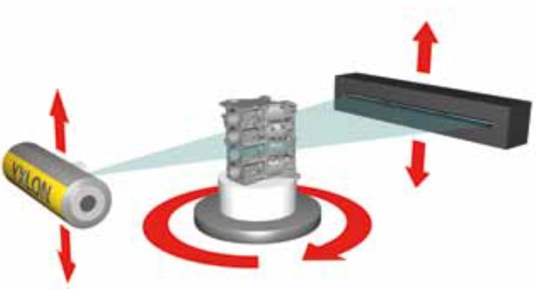
LDA consists of a linear arrangement of sensing elements. These detectors demonstrate particular efficiency at high X-ray energies and can provide an excellent signal-to-noise ratio, making them well-suited for inspecting large and highly dense objects. CT systems utilizing LDAs typically employ a fan-beam CT geometry, where a collimated fan-shaped X-ray beam is used.
Pixel Pitch and Number of Pixels: Resolution in One Dimension. Similar to FPDs, the pixel pitch and the number of pixels in the linear array determine the resolution capabilities of the LDA in one dimension.
Active Length: Determining the Linear Field of View. The active length of the detector array determines the extent of the FOV in the line direction.
Scanning Mechanism: Achieving 3D Data. With LDAs, acquiring a complete 3D CT data set requires mechanical translation and rotation of either the object being inspected or the detector array itself.
✔ Pros:
✅ Good for scanning long objects
✅ Handles thick materials with high-energy X-rays
❌ Cons:
🚫 Requires movement to capture a full image
🚫 Slower than FPDs for imaging
 Combination Detector Systems
Maximum Flexibility for Diverse Needs. Some high-performance industrial CT systems offer the advantage of incorporating both a flat-panel detector and a line detector. This sophisticated configuration provides users with the ultimate flexibility to select the optimal detector for a wide range of inspection tasks. Users can leverage the high speed and versatility of FPDs for certain applications while capitalizing on the high energy efficiency of LDAs for others. Seamless switching between the different detector types is often facilitated through the system’s integrated software.
Which Detector To Choose?
- For 2D X-ray, fast CT scanning output with reducing the inspection time → FPD
- For high-quality image with less noise, especially for the thick or large size object → LDA
5. Differences in the Grayscale of the Detectors
The bit depth of an X-ray detector determines the number of grayscale levels it can capture:
14-bit Detectors: Can capture 16,384 (2¹⁴) shades of grayscale
16-bit Detectors: Can capture 65,536 (2¹⁶) shades of grayscale
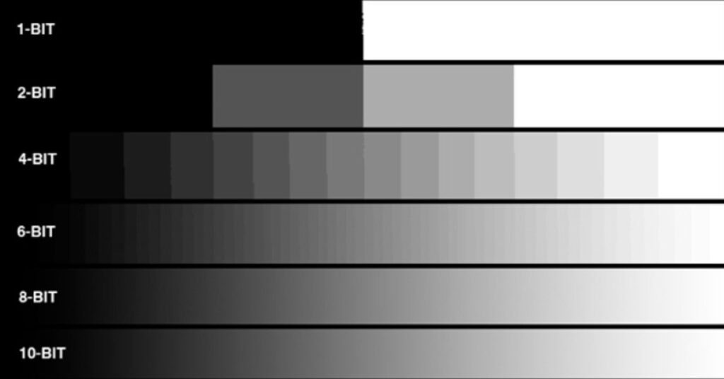
This means a 16-bit detector provides four times the grayscale levels compared to a 14-bit detector, resulting in:
✅ Higher Contrast Resolution – Helps detect subtle variations in material density and small defects.
✅ Improved Image Quality – Enhances clarity, especially in high-precision applications.
✅ Better Data for Image Processing – Useful for advanced analysis, such as CT reconstruction and defect detection.
However, 16-bit detectors typically require higher data processing capabilities and may result in larger file sizes.
Focus Detector Distance (FDD) and Focus Object Distance (FOD)
When performing X-ray or CT inspections, image magnification is an important factor that affects defect visibility, resolution, and accuracy. Focus Detector Distance (FDD) and Focus Object Distance (FOD) directly influence the magnification of the X-ray image. Understanding how to adjust these parameters helps optimize inspection results for different materials and defect sizes.
6. How FDD and FOD Affect the Image Magnification
The X-ray magnification (M) is calculated using the following formula:
M=FDD/FOD
Where:
M = Magnification
FDD (Focus Detector Distance) = Distance from X-ray source to detector
FOD (Focus Object Distance) = Distance from X-ray source to object
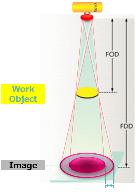
This equation shows that magnification increases as FOD decreases or as FDD increases.
✔ Higher Magnification (Small FOD, Large FDD)
✅ Enhances visibility of fine details
✅ Improves defect detection in small objects
✅ Useful for microfocus and high-resolution X-ray imaging
❌ Potential Downsides:
🚫 Can introduce image distortion and geometric unsharpness
🚫 May reduce field of view (FOV), limiting inspection area
✔ Lower Magnification (Large FOD, Small FDD)
✅ Provides a more accurate size representation of the object
✅ Reduces geometric distortion
✅ Suitable for large objects and accurate dimensional measurement
❌ Potential Downsides:
🚫 Small defects may be harder to detect due to lower resolution
🚫 Less detail in fine structures
Practical Magnification Adjustments
| Increase Magnification | Decrease Magnification | |
| FDD (Focus Detector Distance) | Increase FDD (move detector farther) | Decrease FDD (move detector closer) |
| FOD (Focus Object Distance) | Decrease FOD (move object closer to source) | Increase FOD (move object farther from source) |
✔ To maximize magnification:
Place the object closer to the X-ray source (small FOD)
Move the detector farther from the X-ray source (large FDD)
✔ To minimize magnification (for true-to-size imaging):
Move the object farther from the X-ray source (large FOD)
Place the detector closer to the X-ray source (small FDD)
What kind of X-ray CT Inspection Equipment to Choose?
- The X-ray equipment needs to have an enough length inside the cabinet to ensure a sufficient FDD for magnification analysis of small areas.
Software Capabilities: Enhancing Analysis and Workflow
The software that accompanies the industrial X-ray/CT system is a crucial component that significantly impacts the efficiency of image acquisition, the accuracy of reconstruction algorithms, the effectiveness of analysis tools, and the ease of reporting. Essential software features include image enhancement filters, artifact reduction algorithms, and the ability to create automated inspection routines. These software capabilities are vital for maximizing the information that can be extracted from the X-ray CT system.
7. Image Enhancement and Noise Reduction
X-ray images often contain noise, scatter, and low contrast areas that can make defect detection difficult. Imaging software applies various enhancement techniques to improve visibility.
✔ Key Software Features:
Noise Reduction Filters → Removes grainy textures for clearer images
Contrast Adjustment → Highlights subtle defects in low-density areas
Edge Enhancement → Sharpens fine details, improving crack detection
✔ Impact on Inspection Results:
✅ Enhances defect visibility, making tiny cracks, voids and inclusions easier to detect
✅ Reduces artifacts that could lead to false positives or misinterpretation
What Kind of Software for X-ray CT Inspection System to Choose?
- Software features such as image correction filters can make a big difference in the output result
- Depending on the inspection requirements, software features such as automated inspection capabilities can significantly improve inspection productivity
8. Extended CT Scanning for the large Objects
8-1. What is Extended CT Scanning?
Standard CT scanning is limited by the size of the detector’s field of view (FOV) and the physical movement range of the object or detector. Extended CT scanning overcomes these limitations by using multiple scans, image stitching, or increased motion control to expand the scanning area and improve image resolution.
8-2. Types of Extended CT Scanning
✅ Helical Scan (Spiral Scan)
The object moves continuously through the X-ray beam while rotating, similar to medical CT scans.
Eliminates artifacts caused by stepwise scanning in conventional CT.
Effect: Produces seamless, high-resolution 3D reconstructions with fewer stitching errors.
Best for: Long cylindrical parts like aerospace components, casting parts for automotive as well as pipes.
✅ Offset Scan (Extended Field of View – eFOV CT)
When the object is larger than the detector’s FOV, the CT system captures multiple images and combines them into one.
This method expands the effective scanning diameter without reducing resolution.
Effect: Enables inspection of large parts that do not fit within the standard scanning area.
Best for: Large plastic assemblies, castings, automotive parts, and aerospace components.
Who should use Extended CT?
- If you need to create seamless images for long cylindrical parts in the height direction → Use Helical Scan
- When you need to inspect a large, complex object → Use Offset Scan
Summary
Key Considerations for Selecting the Industrial X-ray / CT System
X-ray Power matches the Material and Size: The density and physical dimensions of the objects you intend to inspect are primary considerations. Denser and larger objects will necessitate the use of higher X-ray tube voltage (kV) and potentially greater power (W) from the source to achieve adequate penetration. Furthermore, larger objects may require detectors with a larger active area to capture the entire object in a single scan or the capability to perform extended field-of-view (FOV) scans.
Required Resolution and Detail Detectability for seeing the Smallest Flaws: For applications demanding the detection of very fine features, such as microcracks, minute voids in electronic assemblies, or subtle material variations, it is essential to choose X-ray sources with a small focal spot (like microfocus or nanofocus tubes) and detectors with a small pixel pitch. The desired level of detail detectability will directly influence the specifications of both the X-ray source and the detector.
Consideration of focus detector distance (FDD) and focus object distance (FOD): When inspecting at high magnification is required, it is necessary to select an X-ray inspection system that can reduce the FOD and enlarge the FDD. On the other hand, when inspecting a wide area at low magnification, a wide-field-of-view equipment that can enlarge the FOD and reduce the FDD is appropriate. By selecting an equipment that matches the size of the object and the purpose of the inspection, it is possible to improve the accuracy and efficiency of defect detection.
Software also influences analysis accuracy and defect detection capability: Key software features include noise reduction filters, contrast adjustment, and edge enhancement, which significantly improve the visibility of defects. This results in improved detection accuracy for microcracks and voids, and reduced false positives. Choosing the right software is essential to obtain high-quality inspection results.
Extended CT scanning technology eliminates the need for multiple section scans of large objects as in conventional CT scanning. By continuously rotating and moving the object relative to itself, the field of view (FOV) can be significantly expanded beyond the detector size in a single CT imaging run. This advanced capability reduces the overall inspection time without being limited by detector size, especially in industrial CT applications with relatively large objects, such as large castings, automotive parts, and aerospace components.
Selecting the appropriate industrial X-ray/CT System is a significant investment that requires a thorough understanding of the specific non-destructive testing requirements and the capabilities of the key system components. By carefully evaluating the different types, specifications, and considerations discussed in this guide, you can make a well-informed decision and invest in a system that will effectively meet the current and future quality assurance and NDT needs. The product range that we are able to offer is all the types of system in this guide, therefore we can discuss together about the suitable NDT systems for customers without favoring any particular product. And also, we are also able to perform sample inspections of the systems to further assist in your selection process.
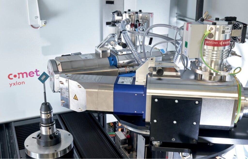
Images source: Comet Yxlon
Phone Contact:
Robin Seino (Mobile Phone: 083 064 2112)
Wanida Petcharat (Mobile Phone: 083 064 6976)
