[3D SCAN] Product Information: Geomagic Design X

About Reverse Engineering
There are various methods for making 3D CAD data from 3D scanned data.
Roughly speaking, the method is as follows.
Preparation:
Edit the scan data (STL mesh)
Scan data cleanup, hole filling, noise processing, thinning, mesh optimization, etc.
Surfacing by the method ①, ② or ③
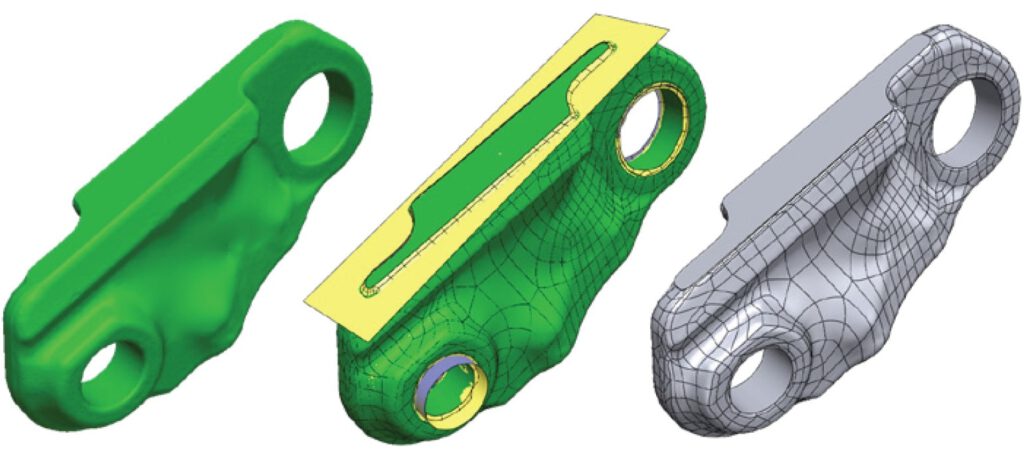
① Auto Surfacing:
We consider converting the file format in order for the scan data (STL file) to be viewed with 3D CAD software as the main purpose. As a result, the surface becomes patchy data, making it difficult in future cases that the 3D model needs to be modified. As an advantage, data can be created in a short time with only one command.
② Boundary Fit:
Surfaces like 3D CAD models are created from the scan data using software tools or manual operations. In some cases, we also create fillets and holes. The 3D model is basically created to faithfully reproduce the scan data.
③ Reverse Modeling:
For example, if the dimension read from the scan data is 4.98, we consider that the original design intent is determined to be 5, so the 3D model is created while modifying it.
We will also correct the inconsistency of the connection surface due to the change.
Therefore, it is very useful if there is a 2D drawing of a similar model available that can be used as a reference.
This high-quality modeling produces close to a 3D model created from scratch. However, the operator requires a certain degree of 3D CAD operation skill.
When a customer requests us to create a 3D model, we think of the modeling method above and have a number of meetings in order to properly understand the required level of data quality. Regarding the above work method for example, in the case of 3D modeling of a mold, a hybrid method is also common, such as creating the product surface according to the scan data, and performing reverse modeling while referring to the 2D drawing dimensions. 3D model deliverables can be Parasolid, STEP or IGES files.
We assume that the customer owns 3D CAD software. If it is possible to receive Parasolid files such as using SOLIDWORKS, we recommend Parasolid files.
Reverse Engineering Software | Geomagic Design X
When it comes to software for reverse engineering, many people would think of 3D Systems’ Geomagic Design X first. It is one of the most used software in the world and we also use it in our services. In addition to the various model creation functions mentioned above, interfaces with the major 3D CAD software are also substantial. For example, Geomagic Design X unique LiveTransfer can transfer all or part of data such as geometry, topology, modeling history, and parameters of a 3D parametric model to the major feature-based CAD software such as Autodesk, AutoCAD, Autodesk Inventor, CATIA, PTC Creo, Siemens NX , Siemens Solid Edge or SOLIDWORKS, etc. automatically and in real time.
What’s new in Geomagic Design X 2022
 From Geomagic Design X version 2022, the logo design has been renewed as a software unified brand called Oqton, which is also the company name acquired by 3D Systems, Inc. in 2022.
Version 2022
 LiveTransfer to Latest CAD Software Versions
The following CAD application versions are additionally supported in LiveTransfer:
• SOLIDWORKS 2022
• Inventor 2021, 2022, and 2023
• Creo 8.0, 9.0
• Creo Parametric 4.0 M150
• NX 1899, 1926, 1953 series
 Improvements to Sketch Tools
Increase the productivity through improved sketching tools allowing you to:
• Draw centered rectangles.
• Replace target mesh when creating or updating mesh sketch.
• Choose display type for circular dimension.
• Define the midpoint constraint between line/arc and point.
 Scanner / Probe Support
With additional hardware support in Scanner Direct Control and LiveCapture, you can now:
• Directly scan objects in Design X using the Hexagon Structured Light Scanner interface.
• Use Scanner Direct Control support for Shining 3D Einscan scanner.
• Probe using Faro Quantum Max/S + LLP XR/HD.
• Use a Leica AT960 tracker + Absolute AS1 scanner.
 Improvements to Modeling Tools
Improvements to the Loft and Exact Surfacing Tools now enable you to:
• Define connectors to have more control over the loft feature definition.
• Choose form options to control tangency for guide curves for Surface Loft command.
• Save time by reusing auto-surface patch networks when creating surface patches manually.
 Region Segmentation
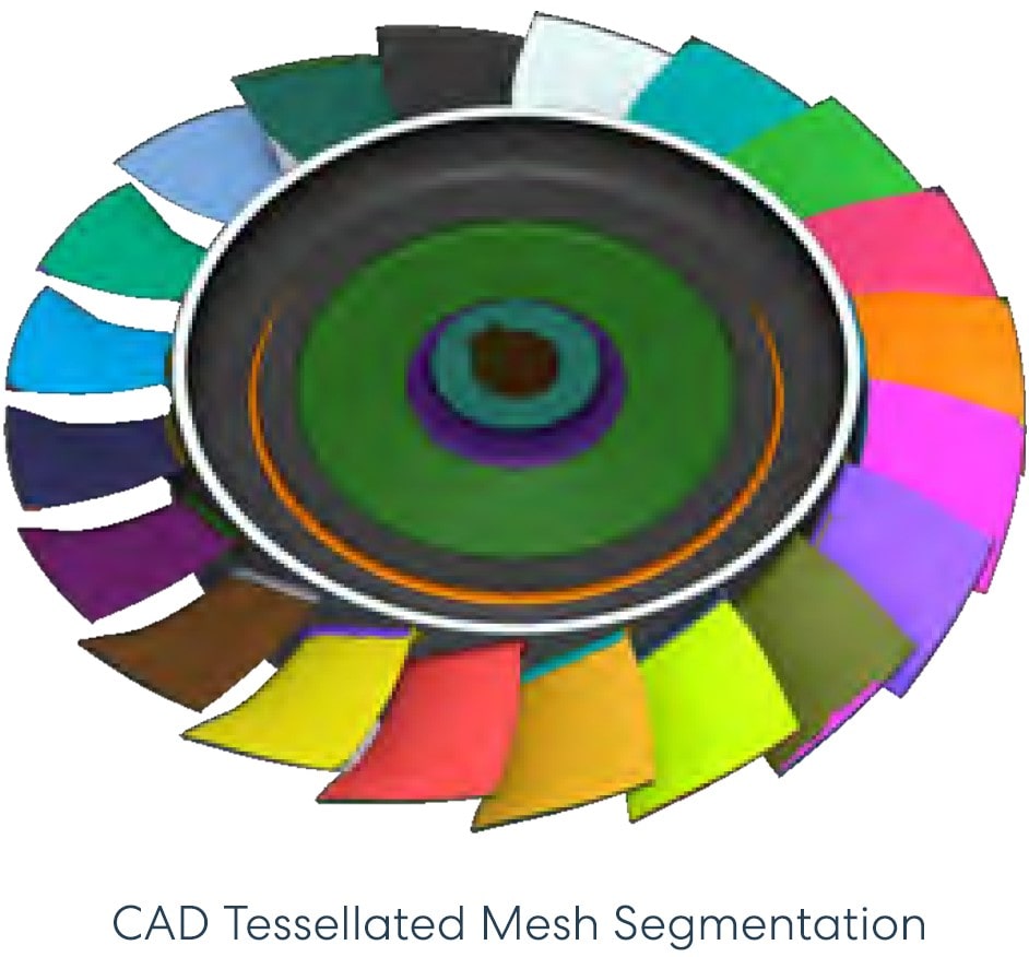
Enhance the quality of region segmentation for a mesh tessellated from CAD with the Design X 2022 new Region Segmentation algorithm. A newly added CAD Tessellation Mesh option allows you to achieve a high-quality region segmentation for the CAD mesh model.
Version 2020
 Selective Surfacing
New selective surfacing capabilities simplify previously difficult part workflows while enabling hybrid modeling workflows. This feature combines a fast organic fit surface method with a highly accurate feature modeling method. As a result, downstream CAD reusability is greatly improved, allowing you to adjust model accuracy and speed up productivity.
• Surfacing bounded by specified curves – gives you more control over where surfaces are trimmed.
• Surface Selected Meshes – Quickly and easily surface only the areas you need.
 Unroll/Roll
New tools such as unfold, flatten and roll simplify modeling of complex revolved geometries. Use comprehensive mesh processing tools to unfold the mesh and automatically extract a 2D sketch, make any necessary modifications, and reroll the sketch for further engineering. This capability not only eliminates the need for multiple iterations and rework, it dramatically improves part accuracy, efficiency, and downstream usability.
 File I/O Update
Geomagic Design X 2020 includes interface enhancements. LiveTransfer has also been updated for connectivity with the latest scanning devices and compatibility with the latest versions of CAD.
• Autodesk® Inventor® 2020
• CATIA® V5/V6 2019 (save as)
• PTC® Creo® 6
• Siemens Solid Edge® 2020
• Siemens® NX™ 1872
• SOLIDWORKS® 2020
 Mesh Separation
A new feature makes it easy to separate a single mesh object into individual elements, making it easier to work with 3D printing and assembly data.
 Extracting Boundary
Curves extracted by the Boundary command can now be explicitly specified as “boundary curves”, thus improving surface quality.
Enhanced surfacing performance
The latest release greatly improves the speed of surface fitting.
• 36% faster auto surfacing
• 28% faster to fit surface patches.
Geomagic Design X Feature Comparison by Editions
| Features | Design X Essentials | Design X |
|---|---|---|
| Import neutral file formats | ✔ | ✔ |
| Extract sectional polylines or silhouette polylines from mesh or point cloud | ✔ | ✔ |
| Create sketch entities based on extracted polylines | ✔ | ✔ |
| Create 3D sketch entities | ✔ | ✔ |
| Mesh processing tools | ✔ | ✔ |
| Create reference geometry | ✔ | ✔ |
| Create solid bodies | ✔ | ✔ |
| Create surface bodies | ✔ | ✔ |
| Basic modeling features | ✔ | ✔ |
| Manual region creation tools | ✔ | ✔ |
| Align meshes or point clouds to other meshes or point clouds | ✔ | ✔ |
| Interactively align mesh using multiple methods | ✔ | ✔ |
| Measurements between entities | ✔ | ✔ |
| Real-time deviation analysis to compare bodies, curves, sketches or meshes with a base entity | ✔ | ✔ |
| Basic selection tools | ✔ | ✔ |
| Automatically create curve networks on the mesh and fit surface patches | ✔ | ✔ |
| Native CAD Importer/Exporter | ✔ | |
| Automatically create sketch entities from section of meshes and point clouds | ✔ | |
| Create 2D sketch independent of a section of meshes and point clouds | ✔ | |
| Create more types of 2D and 3D sketch entities | ✔ | |
| 3D Sketch on the Mesh | ✔ | |
| Wizard for creating mesh models from multiple raw 3D scan data | ✔ | |
| Advanced mesh processing tools | ✔ | |
| Wizard to align a mesh to a desired set of coordinates | ✔ | |
| Automatic alignment methods | ✔ | |
| Transfer design and feature tree to standard CAD software products | ✔ | |
| Plan a series of commands with parameters and run them | ✔ | |
| Execute a series of jobs on a computer without manual intervention | ✔ | |
| Selection techniques based on model properties | ✔ | |
| Automatically create features from a mesh using Modeling Wizard | ✔ | |
| Reform features on an existing design based on reference scan data | ✔ | |
| Advanced surface modeling tools | ✔ | |
| Body/Face editing tools | ✔ | |
| Create surface for a specific portion of the mesh using Auto-Surface | ✔ | |
| Extract a high-quality freeform surface body from a complex mesh | ✔ | |
| Portable metrology device support and tools | ✔ | |
| Direct plugin scanning | ✔ | |
| Automatically classify feature regions by recognizing 3D features from scan data | ✔ | |
| Automatic region modification tools | ✔ | |
| Process point clouds and convert them to a mesh | ✔ | |
| Edit and manage colors and textures on a mesh or point cloud | ✔ | |
| Detect defects on solid and surface bodies | ✔ | |
| Check deviation between meshes and point clouds | ✔ |
We provide both reverse engineering service and software implementation support. Please feel free to contact us if you are interested.
[ CATALOG DOWNLOAD ]
Geomagic Design X Catalog – English
Geomagic Design X Versions Features Comparison – English
Contact Form:
Contact:
Robin Seino (Mobile Phone: 083 064 2112)
Venus Pokasap (Mobile Phone: 087 087 2561)
Wanida Petcharat (Mobile Phone: 083 064 6976)
